Friday, June 20, 2008

Calculating Heat Losses

My Uncle Bob is an intelligent self made octogenarian. After owning a successful business, he retired early and has lived a life of travel and adventure for almost 30 years. Despite working with automation for most of his life, he does not trust anything in the way of new technology and approaches everything new, with tough questions.

When he asked me to scan his home for heating losses I knew right away that I might have to do more than to show him. I was rather reluctant to do this scan as I really did not have much of an idea how I could help him understand. After all, as a thermal imager, all I could do is show him pretty pictures. Undaunted, I spent many hours at his home making lots of pretty pictures. He had many more problems than the pretty pictures of his home that I present here but these thermographs show the worst of his problems.

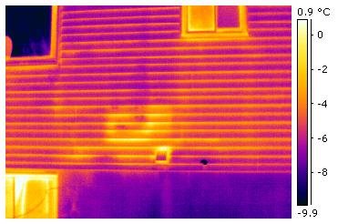
Exterior basement wall which is not insulated on the interior side.

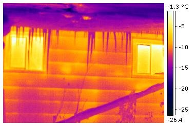
Poor older double sliding windows that are not gas filled and insulating.

Poorly insulated front door entry.

This is the intake and return on the ground source heat pump. The temperature of the intake line is below freezing (it was a cold winter). The efficiency of the heat pump is very poor due to the cold intake temperature which should have been closer to 10 degrees C. which was guaranteed by the installer. The heat pump uses glycol in the lines which prevents freezing.

This home measures well over 3000 square feet and has an indoor pool in the basement which was powering the heat losses in the exterior wall in the first thermograph shown above.

When I take my thermal images, I try to present them so that the eye of the customer is drawn to the items which I want him or her to see. I use Ironbow as the palate because I think it best shows the fault. I spent a day or two compiling all the data and measuring temperatures and presented my Uncle Bob with the report. I could tell right away that my Uncle Bob was unimpressed. No matter how well we do our reports there are just too many cynics in the world. I went home and awaited the inevitable questions. Only one was asked and it was asked sooner than expected.

When I got home there was a message on the answering machine! One question was asked, "How much is this costing me?".

I was a little stumped. Because I was still thinking in terms of temperature, I really did not know how I could help with this. However it did start me thinking on different terms. Instead of temperatures I began to think more of radiation. Our thermal cameras really never see temperature in an object. We can calculate an approximate contact temperature of an object by setting the expected emissivity of our objects, in our cameras. Or we can set the emissivity of the camera to unity (1) and see the 'RADIATING TEMPERATURE' which is the temperature that the object emits to the surrounding environment.

Although our cameras measure temperatures, they actually see and record Infrared Radiation. This is the data that gives us the pretty pictures. Anything in a thermograph that looks warm is Radiating at its surrounding environment and if we capture the temperature of the surrounding environment we can calculate the power transfer from warm to cold. If the heat losses are in stasis the heat losses will be continuous and this means continuous power losses. Depending on changing Radiating temperatures in the surrounding environment, the amount of the power losses will rise or fall.

After several weeks of playing, and with some help from the experts at FLIR Canada, I was able to build templates which can be used to calculate Radiating Heat Losses. The templates are used with the Reporter software that comes with the camera. They enable the quick calculation of Radiating losses of a radiating (or absorbing) object to its surrounding environment. This is the tool I needed to impress my Uncle Bob. The first report generated by this template is shown below.

Exterior Wall Calculated Radiated Heat Loss

This is an estimate of heat loss from infrared radiation on an exterior wall. This calculation will be affected by the size of the warm area and the absorbtion temperature of the cold spot which captures the radiating temperature of the surrounding environment. Convective cooling (wind) on the surface being measured, changing temperatures from day to day and other factors will affect the calculation. This is a snapshot of losses but the actual losses could be SUBSTANTIALLY higher.

Object Parameter                                  Value                                                           

Emissivity                                                 1.0

Label                                                      Value

Cold Spot                                                -18.1 C.

Warm Area                                              -11.0 C.

Fo1                                                           27.8 Watts per square meter

The entire wall, including areas covered by brush and partially hidden, measures 21 square meters. Therefore the total heat lost by this wall is approximately 600 watts per hour at the time the thermograph was taken. These losses will change as the surrounding environment absorbtion temperatures change and will be much greater when the absorbtion temperatures are colder.

Using another developed to measure interior cold spots, I could calculate the power lost by his front door because of poor door insulation.

Interior Wall Calculated Radiating Heat Loss

This is an estimate of heat loss from infrared radiation on an interior wall. This calculation will be affected by the size of the cold area and the radiating temperature of the interior environment which is captured by the warm spot. Convective cooling (wind) on the surface being measured, changing radiating temperatures from day to day and other factors will change the calculation. This is a snapshot of the losses but actual losses could be SUBSTANTIALLY higher.

Object Parameter                             Value

Emissivity                                             1.0

Label                                                  Value

Warm Spot                                          19.8 C.

Cold Area  Average                             15.2 C.

Fo!                                                      26.1 watts per square meter

The size of the cold area on this door is about 2 square meters so the door is losing about 50 watts per hour of power at the time the snapshot temperature was taken.

Sad to say that my Uncle Bob was still unimpressed. His home is still the same today but at least I was able to give him something for numbers. Since all of the walls in his pool area in the basement were uninsulated, after using the templates to calculate the total losses in the basement, the actual losses were close to 3500 watts per hour just in the pool room area. With that number in mind, he decided to make some improvements.

The next entry will look at even more uses of the templates and will give us more numbers to ruminate.                                           

Sunday, June 1, 2008

A Brief Description of Building Dynamics

Before we can look at ways to quantify our heat losses, I think we should look at how building dynamics affect the way we look at those heat losses. First I will introduce a diagram to help with the explanation.


For all of us this is intuitive. (1)When we open a door or window on a wall facing the wind, the wind will blow into the house.(2) Conversely, when we open the same door or window which faces away from the wind, the warm air blows out the door. 

Since the wind blows into the building on the windward side, the same will be true of any leaks in the building envelope on that side of the building. When we look for heating losses on this side of the building they will be seen on the interior wall of the building and will be colder than the interior temperature (or on the exterior wall on the leeward side in summer when the building is air conditioned). In the second case, because the interior pressure is highest on the leeward interior wall and the pressure is the least on the outside wall, we will look for warm spots on the exterior side of the building (or on the interior side of the windward wall in summer when air conditioned). On the sides of the building that see increasing pressures there will be evidence of envelope impingements on both side depending on the interior pressure gradient.

It is important to use the pressure dynamics of the building to discover the best way to use thermal imaging to its advantage. However air is a funny thing. Often losses can be detected on both the outside and inside depending on wind direction and speed. When scanning a building, use your camera all the time and you might find air impingements in spots they are not expected. These breaches may be seen on different floors as cold air might fall down the inside of the envelope.

This small fault (above and to the left of the vent) appears to be along the first floor baseboard. However it was caused by missing insulation from the installation of plumbing for a basement bathroom and this fault was evidenced in the bathroom. The heat losses rose up the interior and are seen above the basement level.

Evidnce of the fault is clearly visible in the new basement bathroom. Cold air is falling down the inside wall to the basement level.

Remember one more thing. Any place where we see cold air on an inside wall or warm air on an outside wall, introduces the possibility of mold growth in the area of the heat exchange. With today's tight envelope homes, this can be a real health problem!

The next entry will look at templates that I have developed to measure the power lost (in watts per square meter) of envelope problems.


Wednesday, April 30, 2008

Our Thermal Environment

We have all felt the effects of thermal energy. When we walk by a camp fire we feel the heat. In winter we may feel a chill indoors when we walk by a window. That window is cold and our bodies radiate at the window and make us cooler. In extreme cases, people can die of hypothermia in the desert because their bodies radiate at the cold sky of night.

All warmth on Earth comes from the sun and that warmth is Solar Infrared Radiation. It warms the land, lakes and oceans and drives the weather we experience. In winter, the amount of thermal radiation we receive in the Northern Hemisphere can be as much as 95 percent less than what we receive in summer. As a result, the radiating environment we live in is much colder in winter.

This first article will show how our radiating environment affects our homes and how the heat losses occur. In order to better understand this heat loss engine we will start with a few rules of heat loss:

1) 60 to 80 percent of heat losses in homes and buildings is Radiated Heat Loss. Heat losses occur through three heat transfer methods: conduction, convection and radiation. In our homes, conduction and convection can drive this heat loss until the lost heat arrives at the exterior wall. At this point the heat will be radiated away from the home.

This home is a newer home which was built to code. However after construction was completed, the builder had to return to replace a defective window. The builder failed to insure the integrity of the 'building envelope' and did not completely repair the insulation and vapor barrier. As a result there is a noticeable loss of heat from the window. The heat travels up the interior of the siding which is heated and radiates to the external environment. The temperature scale on the right side of this thermograph shows the different temperatures of the the siding of this house.

Home interiors can be 'heat sinks' when building envelope is compromised. That means that the radiating temperature of the home can radiate at a cold spot in the walls and transfer energy out of the house.

This homeowner decided to instal a walkway in the attic. The homeowner mistakenly moved the insulation under the boards and the resultant cold spot is evident from that mistake. The home's heating system heats the interior walls and the walls will radiate at this cold spot. That heat will be lost to the home.

In these first two thermographs it is important to note that had these homeowners had the ecoEnergy sponsored blower door test, these faults would not have been detected. There was no evidence of air movement near these envelope breaches. The only way they were found was with an infrared camera. In a later article, we will see how these heat losses can be quantified so the homeowner will have a better idea how much these faults will cost. Now we shall learn about air temperature.

2) Air temperature has almost nothing to do with heat losses. I have now made an assertion which everyone will reject. However, we must look at how air affects our radiating environment and not just at its convective nature. In infrared, air is a transmitter of radiation. What is important is the radiating environment that every wall in the home is subjected too. On the interior of the home, most walls will be at or near room temperature. However, outside walls will all be different because they will each radiate at different objects that they face. Some might be facing other homes, trees or landscapes, Each wall will have a different profile.

This next series of thermographs and pictures will show how much our environment changes in infrared.

These thermographs were taken at about the same time of day. The day was sunny. The air temperature was 0 celsius.

SOUTH FACING WALL(Sunny Side)

The pie plate is used to reflect the radiating temperature of the environment that the wall is radiating at. The wall is heated by the sun to almost 45 degrees Celsius but the pie plate is reflecting an environment that is about -6 degrees Celsius. The environment powers the heat losses on this wall (remember air temperature is about freezing). So we can ask what is this environment?

As can be seen, this side of the home is radiating at shrubs, earth, snow and sky all of which add up to a temperature of -6 Celsius.

NORTH FACING WALL(Shaded side)

This thermograph was taken a few moments later. This wall faces north. Remember, the air temperature is at freezing. However the pie plate reflector has a temperature of about -16 degrees Celsuis. Our North wall is radiating at a completely different environment. This environment will power the heat losses experienced on this wall.

This wall faces a scene made up of water, a distant land mass and the sky and the swans.

In daylight on a sunny day, the sky is always cold (unless facing right into the sun). This thermograph and its radiating temperature is the composite of the warm land on the horizon (about +10 degrees Celsius), cooler water (about 0 degrees Celsius), even cooler clouds (about -15 degrees Celsius) and very cold sky (below -40 degrees Celsuis). The clear sky (not facing the sun) is always this cold in summer and in winter. Which brings us to the next rule.

3) Heat travels from warm to cold. This is the Second Law of Thermodynamics! Whether heat is conducted, convected or Radiated this always holds true. Finally!

4) All building materials used in homes are good to excellent Radiators. Because they are good radiators, when they are colder than the radiating environment they will also be good radiation Absorbers. Wood, fibreglass, glass, aluminium (anodized painted), vinyl, brick and concrete blocks, cast concrete walls and floors and latex and oil based paints can all radiate and absorb at very high rates.

The next article will look at the natural pressure dynamics in a building and how this will affect the radiation losses.